Laminar Air Flow
(LAF Units)
Localised Grade A — ISO Class 5 — Workstation for Non-Hazardous Precision Biology
The Metrolabs Laminar Air Flow unit creates a constant unidirectional stream of H14 HEPA-filtered air across your work surface, establishing a Grade A (ISO Class 5) environment for processes that require absolute protection from ambient particulates — without the containment features of a biosafety cabinet. Available in Vertical Laminar Flow (VLF) and Horizontal Laminar Flow (HLF) configurations to match your specific work process and workspace geometry.
Unidirectional HEPA-Filtered Air — The Barrier Against Particulate Contamination
The core function of a Laminar Air Flow unit is to replace turbulent, unpredictable room air with a steady, unidirectional flow of purified air across the work surface — creating a positive-pressure zone that continuously sweeps ambient particulates away from sensitive samples, media, and precision components before they can settle.
🌬 Turbulent vs Laminar Flow — Why It Matters for Sample Protection
Standard room air is turbulent — it circulates in unpredictable, swirling patterns that carry airborne particles from every direction, including from the operator’s hands, clothing, and breathing zone, onto the work surface and the samples on it. Even in a clean room, turbulent air at the work zone level creates enough particle movement to contaminate an open petri dish, a freshly prepared media plate, or a PCR reaction tube within minutes.
The LAF unit replaces this turbulent environment with laminar (unidirectional, parallel-streamline) flow — HEPA-filtered air that moves in a single direction across the work zone at a controlled velocity. Because the flow is unidirectional and every molecule of air has been through the HEPA filter, no particle can travel against the flow direction to reach the sample from the upstream side — the sample is always in the cleanest air in the work zone, and particles generated by the operator downstream are swept away, not circulated back.
Four Reasons Laminar Flow Achieves What Room Air Cannot
The LAF principle creates sample protection through physical flow dynamics — not filtration of standing air, but continuous replacement of the work zone atmosphere with clean air:
Continuous Air Replacement — Work Zone Is Always Fresh HEPA Air
At 0.45 m/s face velocity, the LAF unit replaces the entire air volume in the work zone approximately 400–600 times per hour — so any particle that enters the work zone from any source (settling, operator movement, item placement) is swept out of the zone within seconds, before it can settle on the sample. The work zone air is not “filtered once and then static” — it is continuously replaced by fresh HEPA-filtered air throughout the working session.
H14 HEPA — 99.997% at 0.3μm — No Particle Bypass
Every cubic metre of air reaching the work zone has passed through the H14 HEPA filter (99.997% filtration efficiency at the 0.3 micron MPPS — the most penetrating particle size). The gel-seal or knife-edge HEPA frame prevents any unfiltered air from bypassing the filter perimeter. The result is that the particle count in the work zone continuously converges toward the Grade A threshold (less than 3,520 particles per cubic metre at 0.5 micron) regardless of the ambient room particle level.
Vibration Isolation — Stable Platform for Precision Work
The motor-blower is mounted with vibration-isolation suspension (calibrated spring and damping system) that prevents blower vibration from transmitting to the work surface. At the specified amplitude of less than 0.002mm, the work surface is stable enough for analytical balance weighing and high-magnification microscopy — two of the most vibration-sensitive operations routinely performed in microbiology and pharmaceutical research settings.
VFD Motor — Constant Velocity as Filter Loads
As the HEPA filter accumulates particles over its service life, its resistance to airflow increases — which in a fixed-speed motor would cause the airflow velocity to drop progressively, degrading the Grade A classification over time. The Variable Frequency Drive (VFD) automatically adjusts the motor-blower speed to compensate for the increasing filter resistance, maintaining the specified face velocity of 0.45 m/s ± 20% throughout the entire HEPA filter service life — so the first hour of operation and the last hour before filter replacement both provide identical Grade A protection.
Vertical vs Horizontal Laminar Flow — Selecting the Right Configuration
The choice between Vertical Laminar Flow (VLF) and Horizontal Laminar Flow (HLF) depends on the geometry of your work process, the height of items on the work surface, and the direction from which the cleanest air should arrive at the sample:
Vertical Laminar Flow (VLF)
Best for: Large equipment, tall instruments, flasks, bioreactor vessels, and centrifuge tubes — where a horizontal air stream would be obstructed by the height of the items, creating turbulence downstream. The VLF configuration handles tall items without any shadow zones or flow disruption, because the downward air simply flows around the item and continues to the perforated base on all sides.
Also preferred for sample work requiring top-access — the operator approaches the work surface from the front and does not interrupt the vertical airflow, because the operator’s hands enter from the side rather than blocking the flow path. The overhead HEPA position maximises light penetration to the work surface — no filter box between the work zone and the overhead lighting creates brighter, shadow-free illumination at the sample level.

Horizontal Laminar Flow (HLF)
Best for: Delicate sample work where the researcher’s hands must be close to the sample and where the sample must be in the cleanest possible air at all times — media preparation, petri dish pouring, sterility test assembly, PCR reaction tube setup, and micro-component assembly. The horizontal flow ensures that the cleanest air reaches the sample before the air has passed over the operator’s hands or any other potential contamination source in the work zone.
The horizontal configuration is also preferred for flat, thin items on the work surface — open plates, membranes, slides — where a vertical downflow might create turbulence at the plate edge that disrupts the flow pattern across the sample surface. The horizontal flow passes smoothly over the plate from back to front without the edge-turbulence that vertical flow creates.
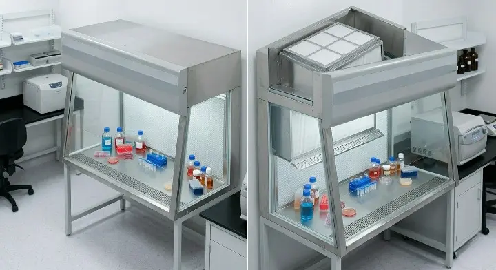
VLF & HLF — Airflow Engineering Schematics
Understanding the airflow path is essential for correct sample placement and optimal Grade A protection in both configurations:


Six Engineering Features of the Metrolabs LAF Unit
Every Metrolabs LAF unit is built to these standards — making it a precision Grade A workstation instrument for long-term pharmaceutical and research performance:
H14 HEPA 99.997% — Tiered G4 + H14 Filtration System
The H14 HEPA filter (EN 1822 rated — 99.997% minimum filtration efficiency at the 0.3 micron MPPS) is installed in a gel-seal or knife-edge frame that prevents any unfiltered air from bypassing the filter perimeter. A G4 pre-filter (95% efficiency down to 5 micron) is installed in the air intake path — capturing large atmospheric dust, pollen, and coarse fibres before they reach the H14 HEPA membrane. This two-stage system extends H14 HEPA service life by 3–5x compared to a single-stage HEPA installation, because the G4 captures the high-mass particle fraction that would otherwise load the H14 rapidly. A differential pressure gauge across the H14 filter provides a visible loading indicator. A factory PAO/DOP integrity test confirms filter and frame performance before the unit is shipped, and the test report is supplied in the IQ documentation package.
VFD Motor-Blower — Constant Air Velocity Over Entire Filter Service Life
The Variable Frequency Drive (VFD) controller continuously monitors the HEPA filter differential pressure and automatically adjusts the motor-blower speed to maintain the specified face velocity (0.45 m/s ± 20%) regardless of filter loading state. In a fixed-speed motor system, the airflow velocity drops progressively as the filter loads — a Grade A qualifying test at the beginning of filter life would pass, while the same test at 75% filter life might fail due to the velocity drop. The VFD eliminates this progressive degradation — the Grade A qualification is maintained from the first operating hour to the final operating hour before the differential pressure alarm signals filter replacement. The VFD also allows the operator to set a standby velocity (typically 50% of operating speed) for idle periods, reducing power consumption and noise during non-work periods while maintaining a positive pressure in the work zone that prevents particle ingress.
SS 304/316L Coved Interior — Zero-Ledge Zero-Joint Construction
The work surface and internal side walls are fabricated from SS 304 (standard) or SS 316L (optional) with all internal corners coved to a continuous radius — eliminating the right-angle junctions where particles and microbial contamination physically accumulate and resist cleaning. A smooth, jointless coved surface is wiped completely in a single pass — the cleaning cloth maintains contact with the surface continuously through the corner radius without repositioning. The mirror-polished or electropolished internal surface (Ra <0.5μm) makes contamination — media residue, disinfectant film — immediately visible under the LED work zone lighting, supporting visual cleaning verification. All components are VHP-compatible at 1000 ppm concentration for facilities using periodic room-wide VHP decontamination cycles.
Vibration < 0.002 mm — Anti-Vibration Platform for Precision Work
The motor-blower is mounted with a vibration-isolation suspension arrangement — calibrated coil springs and damping washers that decouple the blower vibration from the work surface panel. The specified work surface vibration amplitude of less than 0.002mm (2 microns) is the threshold below which an analytical balance with a readability of 0.1mg can record repeatable weighing results without vibration correction — and the threshold below which a standard phase-contrast microscope at 400x magnification produces sharp, focused images without vibration blur. These two operations — gravimetric formulation work and microscopic examination — are the most vibration-sensitive routinely performed inside a LAF unit in pharmaceutical and microbiology settings, and the 0.002mm specification is set to accommodate both without any additional anti-vibration table or foam pad beneath the equipment.
Transparent Side Panels — Safety Glass or UV-Resistant Polycarbonate
The side panels of the LAF work zone are fabricated from toughened safety glass (standard) or UV-resistant polycarbonate (optional for bench-top units where impact resistance is a concern). The transparent side panels serve three functions: they allow maximum ambient light penetration into the work zone from the sides of the unit (supplementing the built-in LED illumination), they allow the operator to see the full work zone from the side without leaning into the airstream, and they allow supervisors and QA personnel to observe the operator’s work technique in the LAF from outside the work zone without disturbing the airflow — a requirement of some GMP SOPs for sterility testing and media fill simulations. The panels are sealed to the frame with the same VHP-compatible silicone as all other sealing points on the unit.
UV-C Germicidal — Automated Idle Decontamination
An optional (standard on pharmaceutical-specification units) UV-C germicidal lamp provides surface decontamination of the LAF work surface and transparent side panels during idle periods between work sessions. The UV-C lamp is activated automatically by the timer or by a keypad input at the end of each work session — the programmed cycle (typically 15–30 minutes for an LAF unit vs the longer 30–60 minutes of a BSC, because the LAF interior is accessible for wipe-down from the front and the UV-C supplements a thorough IPA wipe-down rather than providing the primary decontamination). The UV-C system includes a door or sash interlock — UV-C cannot activate when the front of the unit is open to the operator — and an hour meter for planned lamp replacement. Note: UV-C does not provide the same surface decontamination reach as a hand-wipe, and must always be used in combination with IPA wipe-down, not as a replacement for it.
LAF Unit — Standard Technical Specification
Metrolabs LAF standard parameters — customisable at every dimension and feature:
| Feature | Metrolabs LAF Standard | Benefit |
|---|---|---|
| Interior Material | SS 304 / SS 316L — coved | Corrosion-free · VHP compatible |
| Cleanliness Class✓ Grade A | ISO Class 5 / Grade A | < 3,520 particles/m³ at 0.5μm |
| HEPA Filter | H14 99.997% at 0.3μm | EN 1822 · Gel-seal · PAO tested |
| G4 Pre-Filter | 95% efficiency at 5 micron | Extends H14 life 3–5x |
| Air Velocity | 0.45 m/s ± 20% | VFD maintains over filter life |
| Vibration | < 0.002 mm amplitude | Balance 0.1mg · Microscopy 400x |
| Noise Level | < 65 dB at operator | Comfortable extended work |
| Motor | VFD controlled — auto-compensate | Constant velocity throughout life |
| Side Panels | Toughened safety glass | Max visibility · Impact safe |
| Illumination | LED flush-mounted | No heat · No UV component |
| Configurations | Vertical (VLF) or Horizontal (HLF) | Select for work process |
| Standard Widths | 600 / 900 / 1200 / 1500 mm | Bench-top or ceiling integrated |
| Power Supply | 220 V / 50 Hz | Standard Indian mains supply |
LAF Unit Applications Across Every Non-Hazardous Precision Environment
Grade A ISO Class 5 LAF workstations for every process requiring particulate control without biological containment — for hazardous biological agents, use BSC Class II instead:
Media Preparation
HLF for petri dish pouring, agar preparation, and growth media dispensing into multiwell plates. Sample at the upstream back of the HLF is in the cleanest air as the operator pours. Grade A prevents airborne contamination that causes false-positive microbial growth results.
PCR Setup & Assembly
HLF for PCR reaction tube assembly, master mix preparation, and primer dispensing — where cross-contamination of amplified DNA from previous reactions is the primary contamination concern. Unidirectional horizontal flow prevents amplified product from recirculating to fresh reaction tubes.
Tissue Culture Support
VLF for flask incubation transfer, reagent addition to open plates, and tissue culture accessory preparation — for non-hazardous cell lines where the primary need is sample protection, not operator protection from the cell line. (Hazardous cell lines require BSC Class II.)
Electronics & Semiconductor
VLF for electronic component assembly, wafer die bonding, PCB rework, and MEMS assembly. ISO Class 5 Grade A air prevents particle-induced defects on exposed circuit surfaces. Vibration <0.002mm for wire bonding and microscopy. No biological containment needed.
Analytical Balance Weighing
VLF for gravimetric formulation work, potency assay weighing, and reference standard preparation. Work surface vibration <0.002mm enables analytical balance readability to 0.01mg without vibration correction or additional anti-vibration table. Grade A prevents airborne particle settling on the balance pan.
Optics & Microscopy
VLF for optical component assembly, confocal microscopy sample preparation, and slide mounting. Vibration-isolated blower at <0.002mm amplitude maintains image sharpness at 400x magnification. Transparent side panels allow external observation of sample preparation technique.
Food QC & Sterility Testing
HLF for FSSAI food microbiology non-hazardous sample preparation — standard plate count, yeast and mould enumeration, water testing setups. Grade A protection prevents false positives from ambient contamination. Coved SS 316L interior for food-contact compliance.
Pharmaceutical Compounding
VLF ceiling-integrated for pharmaceutical cleanroom compounding stations where Grade A environment is required at specific work points while maintaining cleanroom pressure cascade. Flush-mounted integration with modular panel system. GMP IQ documentation at handover.
Cleanroom Integration, Custom Configuration & Audit-Ready Documentation
Metrolabs focuses on high-accuracy LAF fabrication and seamless cleanroom integration for pharmaceutical, biotech, and research environments:
Cleanroom Integration — Ceiling-Suspended or Floor-Mounted
Metrolabs LAF units can be ceiling-suspended or floor-mounted to integrate seamlessly with modular cleanroom partition systems — flush-mounted ceiling LAF units that become part of the cleanroom architectural design, maintaining the pressure cascade while providing Grade A zones at specific work areas. The panel-to-LAF junction is sealed with pharmaceutical-grade silicone and is visually inspectable at every cleaning cycle.
Custom Configurations — Anti-Vibration Tables, Perforated Trays, Custom Widths
Metrolabs offers specialised LAF configurations including anti-vibration work surface inserts for balance weighing applications (spring-isolated sub-plates that further isolate specific zones of the work surface from residual vibration), perforated stainless steel work trays for VLF installations where vertical airflow through the work surface is required, and fully custom widths from 400mm to 1800mm to match specific cleanroom bay dimensions.
Audit-Ready IQ Documentation — PAO Test + Velocity Grid + Calibration
Every Metrolabs LAF is factory-validated with a PAO/DOP HEPA filter integrity test (confirming zero bypass at the filter perimeter and frame seal), airflow velocity measurement at multiple work zone grid points (confirming Grade A qualification criteria are met uniformly across the work surface), vibration measurement, and noise level measurement. The factory validation report, material test certificates, and calibration certificates are supplied in the IQ documentation package at handover.
VHP Compatibility — All Components, Every Cycle
All LAF components — gaskets, side panel sealing compound, work surface drain, UV-C end caps, differential pressure gauge connections — are specified and tested for VHP compatibility at 1000 ppm. For pharmaceutical cleanrooms using room-wide VHP as part of their periodic decontamination programme, the LAF can be processed in the same cycle as the room without any disassembly or component protection — maintaining cleanroom uptime between maintenance activities.
LAF vs BSC Class II — Critical Safety Comparison
A Laminar Air Flow unit must NEVER be used for work with infectious agents, pathogens, viruses, bacteria, or any biological material with aerosol hazard potential. An LAF unit does not protect the operator — the air flows toward the operator, carrying any hazardous aerosol generated at the work surface directly to the operator’s face and breathing zone. For all such work, use a Biosafety Cabinet Class II. → View BSC Class II
From Specification to Factory-Tested & IQ-Documented LAF Unit
Metrolabs manages the complete LAF supply and commissioning process:
Specification & Configuration
Airflow direction (VLF / HLF) confirmed for work process. Work surface dimensions, installation type (bench-top / ceiling-suspended / floor-mounted), MOC (SS 304 / SS 316L), optional features (UV-C / anti-vibration insert / perforated tray / custom width), and documentation requirements confirmed. Dimensioned drawing produced and signed off.
Precision Fabrication
Interior fabricated — SS 304 or SS 316L coved. HEPA canopy (VLF) or rear wall (HLF) fabricated and filter housing installed. VFD motor-blower assembled with vibration-isolation mounts. H14 HEPA filter installed in gel-seal frame. G4 pre-filter fitted. Transparent side panels fitted. LED illumination installed. UV-C lamp (if specified). Differential pressure gauges fitted. Passivated per ASTM A967.
Factory Test & Validation
PAO/DOP integrity test on H14 HEPA filter · Airflow velocity measured at work zone grid (multiple points confirming Grade A uniformly) · Vibration measurement at work surface · Noise level at operator position · UV-C interlock test · VFD auto-compensation verified through filter resistance range · All results documented in factory validation report.
IQ Documentation
SS MTCs, ASTM A967 passivation cert, H14 EN 1822 filter cert, PAO/DOP test report, airflow velocity grid measurement, vibration measurement record, noise level measurement, UV-C interlock test record, and commissioning photos compiled for GMP / ISO / NABL laboratory IQ qualification submission at handover.
Factory & Office
4, SIDCO-MICRO, Thirumudivakkam,
Chennai – 600 132, Tamil Nadu
🗺 Open in Google Maps ↗
Phone
Website & GSTN
www.metrolabs.biz
www.schoollabfurniture.com
GSTN: 33AASFM3382K1ZT
Ready to Install a Laminar Air Flow Unit in Your Laboratory?
Contact Metrolabs for a free configuration assessment. Our specialists will confirm your airflow direction (VLF / HLF), work process, dimensions, optional features, and documentation requirements — then fabricate, factory-validate, and supply your LAF unit with complete IQ documentation at delivery.
🔌 Request a Free LAF Unit Quote
Quote Request Received!
Our LAF team will contact you within 24 working hours.
Immediate: 9840931231